Running the computation
When we have everything ready, like sample geometry, materials and source, we can run the calculation. There are may controls that can be used here. First of all, as we are raytracing, we should set the number of rays that will be casted, e.g.
RAYS
1000
This is not necessary the total number of rays that will appear in the computation - most likely some additional rays will be created at interfaces and the final number of rays can be therefore even orders of magnitude higher. The recommended approach to set the value is to start with small number (e.g. 100) and increase it while the output will not be smooth and stable enough (as seen from spectra or from cros-section images).
To set the main computation parameters, we use this directive:
COMP
90.4 90 100 0.359e-9
here it sets the angle of incident beam to 0.4 degrees (measured from the sample surface), ray goes parallel to y axis of the computational space, beam size (for source mode = 0 only) is 100 voxels, and wavelength is 0.359 nm. Note that we use wavelengths instead of energies (that are more common in X-ray field).
Sometimes we don't want to calculate only single value, but an angular scan. The following directive can be used for this, setting the scan start, end and step value:
SCAN_THETA
90.01 91.5 0.01
Note that it is faster to use this regime to scan than to do it manually (e.g. calling xraytrace with different settings in some script), as the global precomputed values are shared in between of calculations. Setting zero angle for start is not recommended, as it might take forever with some source conditions.
If we perform the scan for XSW calculations, we might be interested in normalizing the output to be unity at higher angles (which is sometimes done in literature either for computing or experimental tasks). This can be done using command like this
NORMALIZE
92 3
where a given angle and given material index is used as a base for signals normalization.
MULTSTEP
double
- multiplies the raytracing step by a double. Default is 1, which means approximately a voxel size.
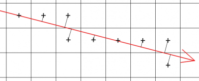
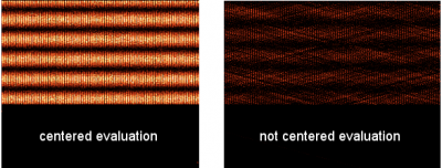
An important setting is centering the voxel evaluations. The rays are propagated using some small steps in the ray direction. If we would evaluate the rays at randomly chosen points (or better say in equidistant intervals not synchronized in any sense with the voxel mesh), we would get quite chaotic behavior, especially for case when the wavelength is similar or smaller than voxel spacing. By performing evaluations at the voxel center we can get reasonable outputs in this case, as shown on the figures below. To switch on the centering, we use command
CENTER
1
To control the algorithm performance for each individual ray we can set also some more parameters. The maximum number of steps in every ray calculation can be set using command like this
MAXSTEP
10000
As the ray progresses by approximately one voxel in each step, this value should not be smaller than size of the computational domain. To control this can be useful in situations where the ray might be trapped in some interference structure.
Similarily, we can control the maximum depth of secondary rays for multiple reflections, which is maximum number of rays produced from one ray (by reflections).
MAXDEPTH
50
The reasonable numbers are around 100, unless we use source method 2 in which ray is recycled many times by the periodic boundary condition and the depth should be therefore significantly higher, e.g. 10000.
Finally, we can shut down all rayw that are of so small intensity that they would not affect the result much. This happens very often with the x-ray reflections. To quit with every ray below 10 percent of the original ray intensity we can set the following parameter:
TERMINATE_LIMIT
0.1
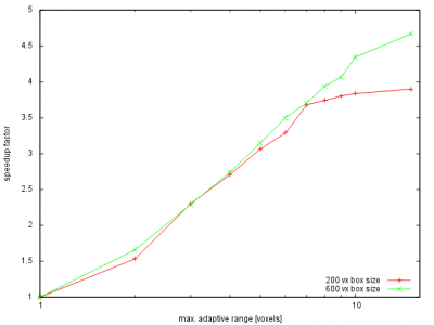
There might a lot of vacuum in between of objects that we want to interact with. The default Xraytrace operation is based on following the ray path voxel by voxel. This is necessary as we want to have general voxel based objects in out computational domain. If we would be treating only analytical objects, we could use 3D analytical geometry tools to search for the boundaries and propagate ray through the vacuum in a single step. The level of generality that we want to keep is therefore a limiting factor in terms of computational demands for single ray propagation. To speedup the calculations we can assign regions in space where ray can be passing faster (as we know in advance that there are no objects). This is done via the speedup command, e.g. to set it to maximum of five voxels like here:
SPEEDUP
5
There are two more debugging comands to be listed in this section:
REGIME
integer
- sets regime of calculation. 0 means illumination only - ray illuminates first material that is not zero and dies. 1 means rays illuminating volume, passing through without any optical effects. 2 means geometrical optics, 3 means only reflections like from perfect metal at any material interface Default value is 2.
VERBOSE
integer
- sets verbosity level. Below 3 this means not many messages and should be used for normal work. Above 3 this means a lot of details of every individual ray. Value of 10 means also debugging data for each ray and no intensity decay in output field data. Default value is 0.


